
- Radio Control
- Servos
- Batteries
- Glow Engines
- Pulsejet
- Turbines
- Electrics
Electrics
Electric powered model aircraft has gained popularity, mainly because the electric motors are more quiet, clean and often easier to start and operate than the combustion motors.
They need batteries to operate and despite some developments in this area; the batteries still are somewhat heavier as energy source compared with the gas fuel.
Thus, the electric flier has to strive to build the model as light as possible in order to obtain a reasonable wing loading and/or a reasonable flight time.
The electric motor's operation is based on the electromagnetic principle. When electric current flows through a coil it creates a magnetic field with a strength proportional to the current's value, the number of windings of the coil and is inversely proportional to the coil's length. The strength of the magnetic field will further increase by introducing a so-called ferromagnetic material inside the coil.
An electromagnetic device only gets magnetic when electric current is applied, whereas a permanent magnet doesn't need electric power to be magnetic.
 Both electromagnets and permanent magnets have the so-called poles at either end. One is called N (north) and the other S (south). When two magnets get close together the N and the S poles attract, whereas the same poles (N N or S S) will repel each other. The electric motor functions according to the same principle.
There are two main different motor types used in model aircraft:
The brushed and the brushless.
 A brushed motor consists mainly of a cylindrical metal case containing a stator and a rotor. The rotor is part of the motor shaft, which rotates inside the stator. The rotor has several coils (poles) that may either have an iron core or are coreless. The stator consists usually of two permanent magnets mounted close to the metal case.
 The rotor coils receive electric current via a so-called commutator, which is connected to a DC voltage through two brushes (hence the name). The commutator changes the voltage polarity to the coils at a certain instant once every turn of the motor shaft, thereby keeping the motor running. The motor shaft is supported by two bearings, which may be of plastic, porous brass bushes or ball bearings (more expensive).
The coreless motor has the rotor coils not wrapped around an iron core but just fastened into shape with glue, which makes the rotor much lighter and faster to accelerate and thus suitable for servos. Since the coreless don't have iron core they have much less iron losses, which make them more efficient than cored motors. However, the coreless motors will not stand continuous high r.p.m. and/or loads without falling apart. That's why they are generally rather small, with low speed and low power. As flight power motors the corless are only used with small indoor planes.
A DC motor converts the electric current into torque and the voltage into rotations per minute (rpm). The power consumption of a DC motor is equal to its terminal voltage times the current. However, every motor has losses, which means that the motor consumes more power than it delivers at its shaft. The motor's efficiency (h) is the ratio of the output to the input power: h = Pout/Pin
Every motor type has an ideal voltage, current and rpm at which the motor's max efficiency is obtained. These values are often shown in the manufacturer's data sheets. Brushed motors efficiency is normally between 30 and 80% depending on the type and price.
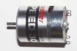 Most motors supplied in kits for beginners have the stator made of low cost ferrite magnetic material. They are called ferrite or "can" motors.
"Can" motors are rather inefficient and cannot be opened and serviced like other higher quality motors. However they are cheap and most kits will fly just fine with these motors, so it's ok to use a "can" motor for your first plane.
 "Rare hearth" motors such as Cobalt and Neodymium are considered to be far superior to ferrite motors, but they are also much more expensive.
Unlike ferrite magnets, the "rare earth" magnets withstand high temperatures without losing their magnetic properties.
Electric motors have several designations such as 280, 300, 400, 480 and 600, which refer to the case length and also give an idea of their power and weight. For example a 480 motor has about 48mm case length, is heavier and is able to deliver more power than a 280 motor.
Generally a 280 motor is suitable to power models up to 400gr and a 480 motor may be suitable to models up to 800gr, while a 600 motor may power models up to 1200gr, assuming direct drive (without gearbox reduction).
As a rule of thumb the input power for a sports plane should be about 110 W/kg (50 to 60 W/lb) in order to get good sport flying characteristics. Gliders and parkflyers may use less power (66 W/kg or 30 W/lb), while pylon racers may need much more power (176 W/kg or 80 W/lb). This assuming that the motor used has at least 70% efficiency.
However, the power to weight ratio recommended above is not by itself enough to determine the plane's performance in flight, as other factors have to be taken into account, such as the minimum pitch speed of the propeller, which is equal to propeller's rpm times the pitch. Minimum pitch speed recommended is 2 to 2.5 times the plane's stall speed.
As a rough estimate one may say that:
Parkflyers fly at 25 - 40km/h (16-25mph) and land at 14 - 24km/h (9-15mph).
Small sport types fly at 30 - 65km/h (20-40mph) and land about 24km/h (15mph).
EDFs fly at 40 - 80km/h (25-50mph) or more and land at about 32km/h (20mph).
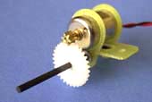 Gearboxes are often used to reduce the motor's rpm at the propeller shaft, increasing their torque and allowing the use of larger propellers. Since the propeller blades also are more efficient at moderate rpm, this combination is often worthwhile despite the increased weight.
Indoors and slow flier models have often a gearbox which allows the use of relatively smaller and lighter motors improving the slow flight performance and prolonging the flight time. The drawback is that the top speed is reduced.
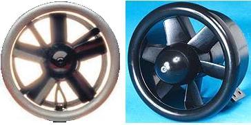 High-speed models such as those powered by Electric Ducted Fans, (EDF) require motors that have their max efficiency at high rpm (typ. above 22.000 rpm).
The flight time of an electric powered model depends on some variables like: Aircraft's flight characteristics (based on wing loading and lift), the combination motor/propeller, the motor's efficiency (Pout/Pin) and last but not the least, the batteries energy/weight ratio. Typical flight time of an average electric powered sports model today (2003) may be between 3 and 8 minutes. Obviously, electric powered gliders will have longer flight times.
Electric flight models may be built small and lightweight enough to fly inside a sports hall. They are the so-called Indoor Models, having approx. 75cm wingspan (30") with a weight less than 200gr (7oz) and flying no faster than 8-16Km/h (5-10mph).
The so-called Park Fliers are somewhat faster. They are often made of foam material and may fly at speeds anywhere from 25Km/h up to about 40Km/h (16 to 25mph). They are rather sensitive to strong winds, so it's recommended to fly them during calm weather.
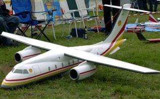
Of course, it's also quite possible to build much bigger electric powered aircraft models.
 As the motor rpm increases it requires the rotor coils to be energised sooner so that they get the full magnetic field strength in time to react with the stator's magnetic field. Also when the load increases, the magnetic field in the rotor coils increases, which interacts with the stator's magnetic field, producing a rotated resultant magnetic field. Some motors allow the brushes' angle to be changed by the same amount as the field rotation, thereby increasing the motor's efficiency under a given load. That's called for motor "timing".
An electric motor may be timed under load by slowly changing the brush holder's angle while measuring the current. The ideal brush angle is when the motor draws less current. There is no fixed ideal timing angle, since the best timing angle changes as the motor load and speed changes. If the motor has been timed at clockwise rotation it has to be re-timed in case the rotation needs to be reversed. The motor's direction of rotation may be reversed by inverting the voltage polarity at the supply terminals. A timed motor gets higher idle current (with no load).
Brushed motors need some maintenance, since both the brushes and the comm. will wear after a while due to the friction. Most quality motors allow brush replacement. The commutator itself also needs cleaning as it gathers deposits of carbon and gunk due to the graphite powder from the brushes. It may be cleaned by a very light polishing action with scotchbrite or with a so- called commutator stick. The gunk can also be cleaned off while the motor is running manually, using a few drops of alcohol. If commutator is pitted or shows brush skipping and chattering means that it has been overheated and got deformed (out of round). It needs to be repaired, as polishing will not cure the deformation.
Brushes are usually made of three different compounds:
- Silver brushes are normally used in competitive racing as they have low resistance, but they produce the highest commutator wear and also have medium brush wear and lubrication. Silver brushes produce sludge that only can be removed by lathing the commutator.
- Copper brushes don't produce sludge and work best at high rpm. These brushes produce medium commutator wear and have high brush wear and low lubrication.
- Graphite brushes produce low commutator wear, have low brush wear and high lubrication but have high resistance, which means that they are not suitable for racing.
Usually it's necessary to "break-in" a new brushed motor so that the flat brushes get a curved surface and thus increasing the contact area with the commutator. Running a motor with new flat brushes at full load will cause a lot of arcing, which pits the contact surfaces and degrades performance. The "break-in" may be done by running the motor without load (without prop), at about 1/2 its rated voltage for about a hour or two. The brushes should get a curved surface without sparks/arcing. Some high-quality motors do not need to be "broken-in". This will be mentioned in the respective motor's manual. In case of doubt, just break it in.
 Sparks that occur between the brushes and the commutator can cause radio interference. In order to prevent radio interference it is recommended the use of ceramic capacitors soldered between each motor terminal and the motor case. For extra security against interference, a third capacitor should also be fitted between the motor terminals.
Note: many Graupner Speed xxx motors have the first 2 of these capacitors already fitted internally.
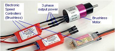
A common way to control the electric motor's speed is by using an Electronic Speed Controller (ESC).
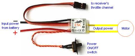
 The Electronic Speed Controller is based on Pulse Width Modulation (PWM), which means that the motor's rpm is regulated by varying the pulses' duty-cycle according to the transmitter's throttle position.
For example, with the throttle at the minimum position, there will be no pulses, while moving the throttle to the middle will produce 50% duty-cycle. With the throttle at the max position the motor will get a continuous DC voltage.
Most ESCs have a facility known as Battery Eliminator Circuit (BEC). These controllers include a 5V regulator to supply the receiver and servos from the same battery that is used to power the motor, thereby eliminating the weight of a second battery only to power the radio and servos. The motor power is cut-off when the battery voltage falls, for example below 5V. This prevents the battery from getting totally flat allowing the pilot to control the model when the motor stops. Some controllers also include a brake function that prevents the propeller from keeping spinning when the motor power is cut-off. Electronic Speed Controllers are available in different sizes and weights, which depends on their max output current capabilities. Another important characteristic of an ESC is the on-resistance of the output power switching transistor(s). The on-resistance should be as low as possible, since its value is proportional to the power loss dissipated by the output transistor(s): P = R x I2
The on-resistance is normally between approx. 0.012 and 0.0010ohm. The value depends on how many output parallel-connected transistors the actual ESC has. The higher the current capability the lower the on-resistance should be. These figures are normally shown on the ESC data sheet along with the BEC voltage cut-off value and the max. output current to the receiver and servos.
As a safety measure many ESCs have a function that won't allow the motor to start running unless the throttle is initially set in the minimum position. Another safety device is the so-called arming switch connected between the motor and the controller. The arming switch should be off until the plane is ready to taxi out on the runway or be hand-launched. After the flight, the arming switch should be turned off as soon as possible. This will prevent the motor from start running in case the throttle stick is moved forward unintentionally.
In order to keep the arming switch contacts in good shape (lowest resistance) it's advisable to never switch it on/off under power. This means that the arming switch should be only turned on/off when the throttle is in the minimum position.
The more powerful the motor, the more need for the safety of an arming switch. A reasonable approach is using an arming switch on flight models larger than speed 400 size (approximately 100 watts and above).
Large batteries are capable of delivering very high currents when shorted or when the propeller gets blocked. Such high currents are enough to overheat and melt components/wiring, which may lead to a fire. Some organisations that provide insurance for modellers require a fuse in electrically powered models. To choose the correct rating for the fuse just put the largest and highest-pitch prop that you expect to fly with. Measure the current draw of your power system on the bench and multiply the value by about 1.25. This 25% margin should prevent nuisance blows. Find the fuse with a rating at or just above this current level.
 Another type of electric motors for model aircraft are the so-called brushless.
These motors are rather expensive, but they have higher efficiency. Typically between 80 to 90%. Since they have no brushes, there is less friction and virtually no parts to wear, apart from the bearings.
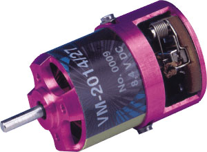
 Unlike the DC brushed motor, the stator of the AC brushless motor has coils, and the rotor consists normally of two permanent magnets. The stator of a conventional brushless motor is part of its outer case while the rotor rotates inside it. The metal case acts as a heat-sink, radiating the heat generated by the stator coils and keeping the permanent magnets at lower temperature.
 They are 3-phase AC synchronous motors. Three alternated voltages are applied to the stator's coils sequentially (by phase shift) creating a rotating magnetic field which is followed by the rotor.
It's required an electronic speed controller specially designed for the brushless motors, which converts the battery's DC voltage into three pulsed voltage lines that are 120o out of phase. The brushless motor's max rpm is dependent on the 3-phase's frequency and on the number of poles:
rpm = 2 x frequency x 60/number of poles. Increasing the number of poles will decrease the max rpm but increase the torque.
The standard brushless speed controller varies the speed of the motor by varying the phase pulse-width according to the transmitter's throttle position. At full throttle each phase pulse has it's max width giving the max rpm and torque.
A brushless motor's direction of rotation can be reversed by just swapping two of the three phases.
 Earlier speed controllers needed an additional set of smaller wires connected to the motors' internal sensors in order to determine the rotor position to generate the right phase sequence. New controllers read the so-called "back EMF" from each phase, which allows the motor to be controlled without the need of the extra wires and sensors. These new controllers are called "sensorless" and can be used to control motors with or without internal sensors.
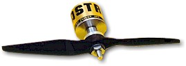
A recent type of brushless motor is the so-called "outrunner". These motors have the rotor "outside" as part of a rotating outer case and the stator is located inside the rotor. This arrangement generates much higher torque than the conventional brushless motors, which means that the "outrunners" are able to drive larger and more efficient propellers without the need of gearboxes.